
In oilfield hydraulic systems operating at 10,000 PSI, leakage is not a maintenance concern—it is a system-level failure risk. These systems power critical equipment such as blowout preventers (BOPs), wellhead control units, and subsea modules, where even minor leakage can lead to pressure loss, environmental contamination, equipment damage, and costly downtime.
At this pressure level, traditional hydraulic architectures reach their limits. The issue is not component quality, but system design complexity.
Why Leakage Becomes Inevitable in Traditional Systems
Leakage in high-pressure systems is structural, not accidental. The root cause is the way traditional systems are assembled.
A typical hydraulic circuit relies on a large number of threaded fittings, adapters, and tubing connections. Each interface introduces a potential leak path—especially under vibration, pressure pulsation, and thermal cycling. At 10,000 PSI, even microscopic imperfections or slight misalignment from tolerance stack-up can create leakage pathways.
Sealing elements further compound the problem. Elastomeric seals degrade over time due to pressure, temperature, and chemical exposure (e.g., hydrocarbons or H₂S), leading to extrusion, compression set, or rapid gas decompression failure.
Key engineering reality:
The more connections a system has, the higher its probability of failure.
How Custom Manifold Blocks Eliminate Leakage
Custom manifold blocks address leakage at the system architecture level, primarily by eliminating failure points and stabilizing sealing conditions.
1. Connection Elimination (Primary Mechanism)
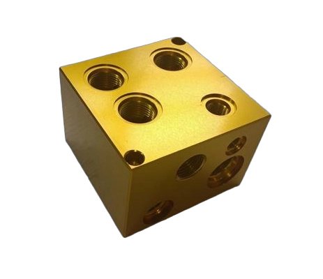
The most significant improvement comes from consolidation. Instead of using dozens of external fittings, a manifold integrates flow paths into a single solid block through internal drilled galleries.
This design typically reduces external leak paths by 70–90%, directly removing the most common sources of failure rather than attempting to reinforce them.
2. Precision Machining and Sealing Integrity
At 10,000 PSI, sealing reliability depends on geometric accuracy. Custom manifolds are machined to tight tolerances (up to ±0.001 in), ensuring proper alignment between ports and components.
This level of precision:
- Eliminates micro-gaps
- Ensures consistent seal compression
- Reduces sensitivity to assembly error
Instead of relying on installer-dependent thread sealing, manifolds use engineered sealing geometries such as face seals, gland seals, and controlled O-ring grooves.
3. Material and Structural Reliability
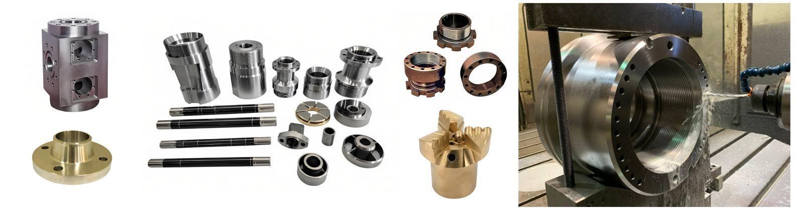
Material failure is a direct leakage pathway at high pressure. Custom manifolds are machined from forged high-strength alloys such as 4140/4340 steel, 316/17-4 stainless steel, or Super Duplex materials for corrosive environments.
Compared to assembled piping systems, the monolithic structure provides:
- Higher resistance to deformation
- Elimination of internal porosity (common in cast parts)
- Improved fatigue life under cyclic loading
For sour service environments, compliance with NACE MR0175 ensures resistance to sulfide stress cracking.
4. Flow Optimization and Pressure Stability
Internal flow paths in a manifold can be engineered to reduce turbulence, pressure spikes, and dead zones—conditions that accelerate seal wear and induce leakage.
Smooth, deburring manifold blocks (via processes like abrasive flow machining) improve flow stability and reduce localized stress on sealing surfaces, contributing to longer system life.
5. Vibration and Fatigue Resistance
Traditional piping systems behave like flexible structures under vibration, leading to loosening and fatigue at joints. In contrast, a manifold block acts as a rigid body with minimal stress concentration.
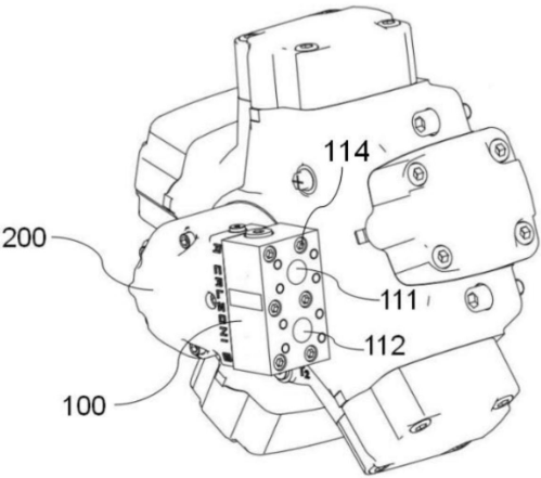
Additionally, cartridge valve integration places critical sealing interfaces inside the block, protecting them from external mechanical loads.
6. Advanced Sealing for Extreme Conditions
For high-pressure and subsea applications, custom manifolds enable the use of metal-to-metal sealing systems (e.g., C-seals, BX gaskets), which outperform elastomeric seals in high-temperature and high-pressure environments.
Processes such as autofrettage can further enhance fatigue resistance by pre-stressing internal bores.
7. Validation and Reliability Assurance
Custom manifold systems are validated through hydrostatic testing, leak detection, and dimensional inspection, in accordance with API, ISO, and ASME standards. This ensures consistent performance under extreme operating conditions.
Custom Manifold vs. Traditional System
| Aspect | Traditional System | Custom Manifold |
|---|---|---|
| Leak Risk | High (many interfaces) | Low (integrated design) |
| Structural Stability | Flexible, fatigue-prone | Rigid, fatigue-resistant |
| Sealing Method | Thread-dependent | Engineered sealing |
| Maintenance | Frequent | Reduced |
| System Efficiency | Lower | Higher |
Engineering Conclusion
At 10,000 PSI, leakage is not a sealing problem—it is a design problem.
Custom manifold blocks eliminate leakage not by improving individual components, but by:
- Reducing connection count
- Controlling geometry and tolerances
- Integrating sealing systems
- Stabilizing structure under load
This transforms hydraulic reliability from a maintenance challenge into a design-controlled outcome.
