
In fluid power and pneumatic system design, manifold blocks are critical components for distributing air or vacuum efficiently across multiple channels. Two commonly compared configurations are air manifold blocks and vacuum manifold blocks. Although they share structural similarities, their engineering requirements, performance characteristics, and application contexts differ significantly.
This article provides a technically rigorous comparison optimized for both search intent and engineering decision-making, covering definitions, structural differences, performance parameters, real-world applications, and selection guidelines.
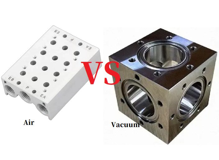
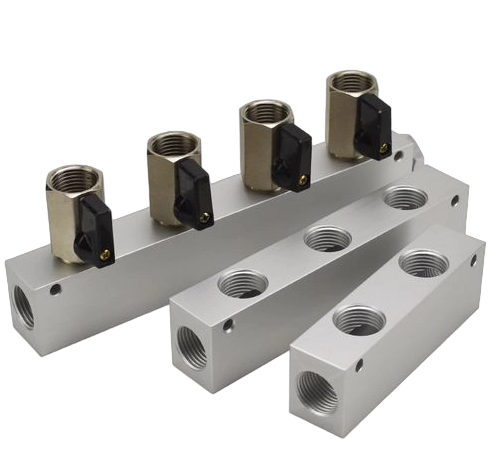
What Is an Air Manifold Block?
An air manifold block is a centralized distribution component used in compressed air systems. It channels pressurized air from a single inlet into multiple outlets, typically feeding pneumatic actuators, valves, or tools.
Key Characteristics
- Designed for positive pressure systems (typically 4–10 bar in industrial settings)
- Often integrated with solenoid valves
- Constructed from aluminum, stainless steel, or engineered plastics
- Supports high flow rates with minimal pressure drop
Typical Applications
- Industrial automation lines
- CNC machinery
- Packaging systems
- Pneumatic control panels
What Is a Vacuum Manifold Block?
A vacuum manifold block distributes negative pressure (vacuum) from a pump or ejector to multiple suction points. It is widely used in pick-and-place systems and material handling.
Key Characteristics
- Designed for negative pressure (vacuum), typically −60 to −100 kPa
- Requires airtight sealing to prevent leakage
- Often includes check valves, filters, and vacuum sensors
- Optimized for leak minimization rather than high flow
Typical Applications
- Robotic vacuum gripping systems
- Semiconductor manufacturing
- Medical suction devices
- Vacuum packaging
Core Differences: Air vs Vacuum Manifold Blocks
| Parameter | Air Manifold Block | Vacuum Manifold Block |
|---|---|---|
| Pressure Type | Positive pressure | Negative pressure (vacuum) |
| Design Priority | Flow efficiency | Leak prevention |
| Sealing Requirements | Moderate | Extremely high |
| Typical Materials | Aluminum, brass | Aluminum, stainless steel with seals |
| Valve Integration | Solenoid valves | Vacuum generators, check valves |
| Failure Mode | Pressure loss | Vacuum decay (leak-driven) |
Engineering Design Considerations
1. Flow Dynamics vs Leak Sensitivity
Air systems prioritize flow rate (Cv value) and pressure stability. In contrast, vacuum systems are highly sensitive to even micro-leaks.
- A 1 mm leak in a vacuum system can reduce holding force by up to 30%
- The same leak in a compressed air system often has negligible impact
2. Sealing Technology
Vacuum manifolds typically require:
- O-rings with lower permeability (e.g., FKM, EPDM)
- Surface finish < Ra 0.8 µm for sealing interfaces
Air manifolds can tolerate less stringent sealing due to outward pressure.
3. Port Configuration
- Air manifolds often use parallel distribution
- Vacuum manifolds may use segmented zones to isolate suction loss
4. Energy Efficiency
Vacuum systems are inherently less energy-efficient:
- Generating vacuum via ejectors can consume 2–4× more compressed air
- Poor manifold design can increase energy consumption by 15–25%
Real Engineering Case Study
Automated Pick-and-Place System
Scenario: A robotic system handling glass panels using vacuum suction cups.
- Original design used a standard air manifold retrofitted for vacuum
- Observed issue: vacuum drop from −85 kPa to −60 kPa under load
Root Cause
- Internal leakage due to inadequate sealing geometry
- No check valves to isolate suction zones
Solution
- Replaced with a dedicated vacuum manifold block featuring:
- Integrated check valves
- Optimized sealing grooves
- Zoned distribution
Result
- Vacuum stability improved to −82 kPa ±2 kPa
- Cycle failure rate reduced by 18%
- Energy consumption reduced by 12%
When to Use Each Type
Choose an Air Manifold Block When:
- System operates under positive pressure
- High flow rate and fast actuation are required
- Minor leakage is tolerable
Choose a Vacuum Manifold Block When:
- System relies on suction or holding force
- Leak prevention is critical
- Stability of negative pressure impacts product quality or safety
Hybrid Systems: Combined Air and Vacuum Manifolds
In advanced automation systems, both manifold types may coexist:
- Air manifold drives pneumatic actuators
- Vacuum manifold handles gripping tasks
Designers should:
- Physically separate circuits
- Avoid cross-contamination of pressure regimes
- Use dedicated sealing and port standards
Selection Checklist
When specifying a manifold block, consider:
- Operating pressure range (positive vs negative)
- Flow rate requirements
- Leak tolerance
- Material compatibility (corrosion, temperature)
- Integration needs (valves, sensors, fittings)
- Maintenance accessibility
Conclusion
While air manifold blocks and vacuum manifold blocks may appear structurally similar, they are engineered for fundamentally different physical regimes. Misapplication can lead to performance degradation, energy inefficiency, and system instability.
For optimal system performance:
- Use air manifolds for distribution efficiency under pressure
- Use vacuum manifolds for precision suction and leak-sensitive environments
Understanding these distinctions ensures better system reliability, lower operational costs, and improved engineering outcomes.
